
|
|
 |
|
|
|
Welcome to the Australian Ford Forums forum. You are currently viewing our boards as a guest which gives you limited access to view most discussions and inserts advertising. By joining our free community you will have access to post topics, communicate privately with other members, respond to polls, upload content and access many other special features without post based advertising banners. Registration is simple and absolutely free so please, join our community today! If you have any problems with the registration process or your account login, please contact us. Please Note: All new registrations go through a manual approval queue to keep spammers out. This is checked twice each day so there will be a delay before your registration is activated. |
|
|||||||
| The Pub For General Automotive Related Talk |
 |
|
|
Thread Tools | Display Modes |
|
|
#31 | ||
|
FAWD - No Boundaries
 Join Date: Jun 2010
Location: Adelaide
Posts: 8,129
|
Howdy. Three things here.
1. It is possible to rejig the circuit board inside the wheel mounted switch pods. I had to rework the audio pod circuit board and change all the FG resistance values to BA/F, when I fitted the FG wheel to my BF, so the buttons would work with the BF ICC. 2. If you need a few more wires to connect the steering wheel to the column... there is some room left in the clock spring. Basically... The spare wire locations in the steering wheel-clockspring plug are already "wired" through the clock spring... waiting to be used for something. 3. I wasn't actually suggesting reassigning any existing buttons off the switch pods. When I said steering wheel mounted paddles before... I meant new paddles mounted to the steering wheel. Hope this made sense  D
__________________
View My Build thread 22 DJR Shell V-Power Mustang Eskymobile (my first EV) 07 BF2 AWD Falcon Wagon (Daily driver) 04 BA Falcon 1Tonner Ute (New Project) 03 BA Falcon Wagon (Spare) 98 NL Fairlane Ghia V8 (Weekend cruiser) 70 VG paddock racer (Cain it til it breaks.. fix it.. Cain it all over again !)
|
||
|
|

|
| This user likes this post: |
|
|
#32 | ||
|
FAWD - No Boundaries
 Join Date: Jun 2010
Location: Adelaide
Posts: 8,129
|
I reckon the hardest part of doing a paddle sift mod would be to find/ mount some paddle shift buttons on the wheel that look like they're meant to be there and the fitting is robust enough to put up with its use.
I had a quick look into this once (not a good look) and thought the paddle shift buttons on an SZ Commy wheel looked like they could be utilised !?? Whatever the set-up is used... The resistance values just need to be matched to the sports shift resistance values (if any??).... and it should work. As I said... I've only had a quick look into this... I haven't gone so far as to test for resistance values yet.... or tried to mount any paddle s to the wheel. D
__________________
View My Build thread 22 DJR Shell V-Power Mustang Eskymobile (my first EV) 07 BF2 AWD Falcon Wagon (Daily driver) 04 BA Falcon 1Tonner Ute (New Project) 03 BA Falcon Wagon (Spare) 98 NL Fairlane Ghia V8 (Weekend cruiser) 70 VG paddock racer (Cain it til it breaks.. fix it.. Cain it all over again !)
|
||
|
|

|
|
|
#33 | ||
|
FF.Com.Au Hardcore
Join Date: Jan 2012
Posts: 509
|
I have one of the no longer available Ebay kits at home still boxed and never fitted. Make me an offer....
__________________
ďIf I had asked people what they wanted, they would have said faster horses.Ē ― Henry Ford |
||
|
|

|
|
|
#34 | ||
|
Away on leave
Join Date: Apr 2019
Location: ACT
Posts: 1,735
|
My FG (MK2) ZF flappy paddles...
I started seriously thinking about flappy paddles for my [one owner, 43,000km's  ] 2012 FG MK2 XR6T (LE) a few months ago. I had seen the flappy paddle mod available on ebay a few years ago that was stuck high up on the steering wheel column, but I didn't like it for a few reasons I won't go into here. It's good to have a red hot go after all, and good on 'em for making it. ] 2012 FG MK2 XR6T (LE) a few months ago. I had seen the flappy paddle mod available on ebay a few years ago that was stuck high up on the steering wheel column, but I didn't like it for a few reasons I won't go into here. It's good to have a red hot go after all, and good on 'em for making it.I've also been playing around with some microcontrollers for years now for various projects, and have moved on through some different models from the old Mega328P 16MHz based ones to some nice ESP8266 WiFi modules that run much faster and even on to ESP32S that are fantastic. Here though, the cheap ESP8266 ones came to mind for sending radio signals from inside the steering wheel to the gear shifter, which seemed like a neat way to implement some paddles without a lot of extra wires... Until I worked out the only power source inside the steering wheel was the horn's 12v wire, through its relay coil. So I started thinking from scratch again, not wanting to mess with the horn. At this stage I was convinced that I'm very limited with respect to mounting something new on the steering wheel itself - but I then thought there's already some buttons on the wheel which I could re-purpose (no, I hadn't searched any forums for ideas, but once I was done I did find this forum thread that also shares the same idea). I ordered some original FG steering wheel buttons from ebay to play around with, because I really didn't want to screw with my car at all. I can see they are a pair of resistor-to-resistor networks that change total resistance depending on the button pressed. The nice thing here is, only one button will be detected at a time on each side (press two on one side and one button always takes priority)... I recorded the values I saw with my meter and calculated the differences. Only later, I found a download for the car's wiring schematics that had all this information! Hmmm, back to the trusty Mega328P. It has the ability to interface with these types of analog signals fairly easily, it has loads of output pins that might be needed, so I coded up some firmware to report back which buttons were being pressed. Easy. My next problem to solve though was keeping as much functionality in the car as I could, which meant solving a few problems: 1/ How to replicate back to the car what the buttons were originally doing, but by using the microcontroller. 2/ How to detect what mode the car was in (Auto/Sports, and if the gear shift +/- was currently in use). 3/ How to control the +/- functions of the gear box from the microcontroller. 4/ How to prevent limp mode if the transmission sees some signals that shouldn't happen. 5/ How to install this device without screwing with the car in a permanent way! Point 1 was a bit tricky as I didn't know much about the car's wiring. After reading the wiring schematics, it also turns out my car is different to the documentation... The steering column [clock spring] socket: 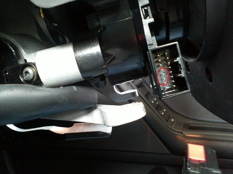 has 4 pins in a row for the two sets of buttons, which when I look at the schematic, go [GND, L-Signal, GND, R-Signal] but my car has them wired up as [GND, L-Signal, R-Signal, GND]! My initial thoughts of using some signal level transistors would surely not like being plugged in without knowing exactly which wires were which because the polarity matters. Here's the car's plug that goes into the clock spring socket:  This is the circuit that is drawn differently to how my car was built: 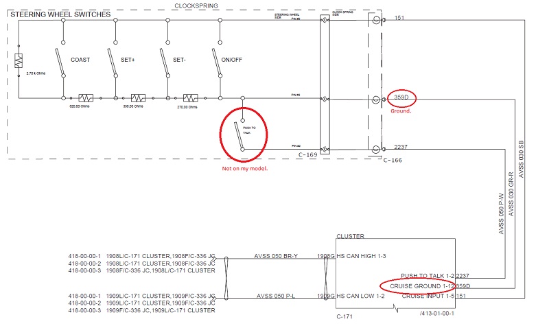 You can see pin 359D=ground and 151=signal in the diagram (my car doesn't have pin 2237 or the push-to-talk button). Here is the plug's pinout, where on my car 151=ground and 359D=signal. Both my car and the schematic diagrams show the radio buttons as being on 1204=ground and 729=signal so that's good. From what I can see, 1B=horn-relay (+12v) and 57CN=horn-ground. 1B, 614, 615, 1516 & 1517 are used for the steering wheel's air bag. 14KD is unknown to me! I can see an extra wire too on my plug, which isn't documented. 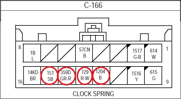 Thinking about how point 5 could be solved, I'm going to isolate those 4 pins I need using an interface board. Since the original plug won't be fully inserted [and locked in place] anymore, I need to work out how to use a wire tie to keep it all together - I've wrapped it around as shown here: 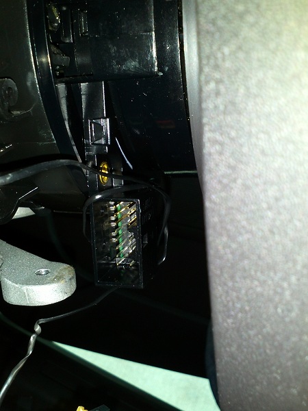 But wait, what's that inside the socket? Turns out, it's 3 fail safe sprung metal tab "switches" to tell if the plug is loose, which can give an airbag warning: 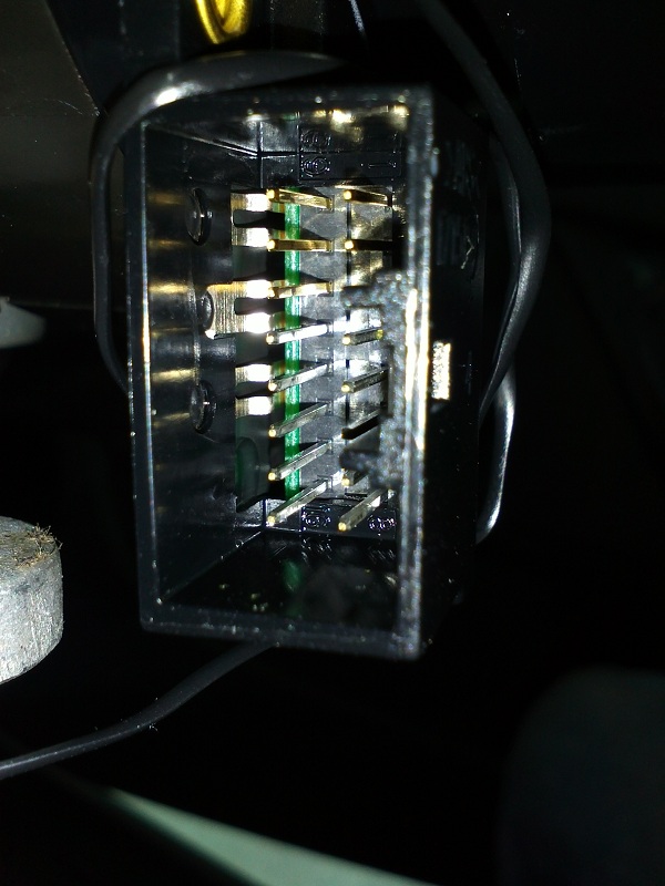 My interface board and kapton electrical tape insulator (on thick-ish paper card) to bypass those fail safe switches: 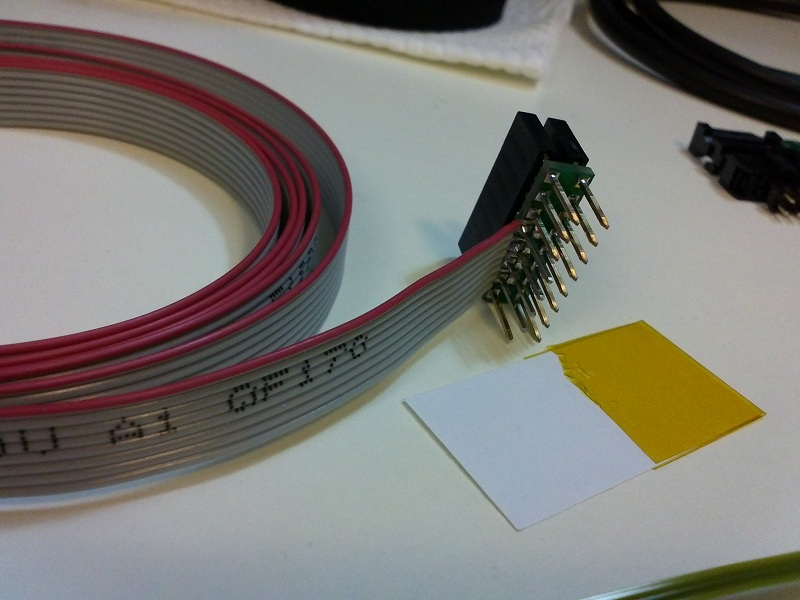 My full kit, almost finished. Here, I'm going to use thick copper wire [on the right hand end of the grey ribbon wire shown in the middle] to interface with the existing transmission shifter plug - so I don't have to cut any of my car's wires or do any soldering to the car: 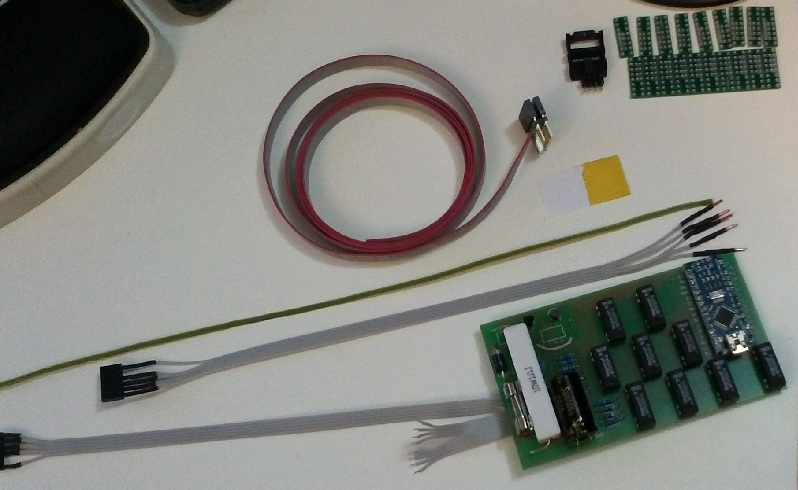 Close up of the thick copper wire: 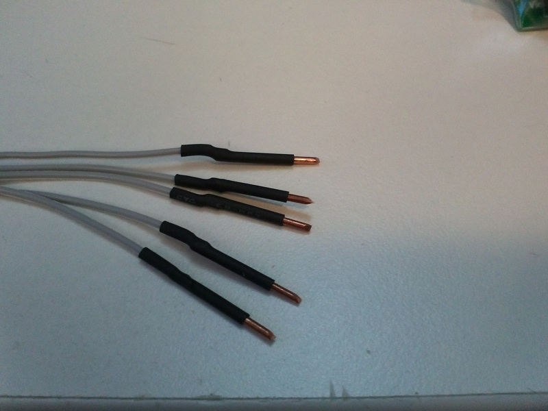 I'm also now testing another design with signal transistors for the R-to-R resistor button networks, to be used if it's known how the car's steering wheel plug is wired - $45 extra in relays for the first model just sucks. This one is wrapped in heat shrink tubing and is a much smaller circuit board to the first one I made earlier: 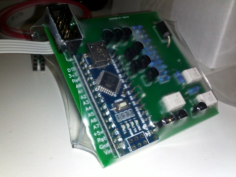 Back to the steering wheel... Insulator paper card fully inserted to make sure the 3 metal tabs don't short out the plug's wires (which the car detects as a loose plug): 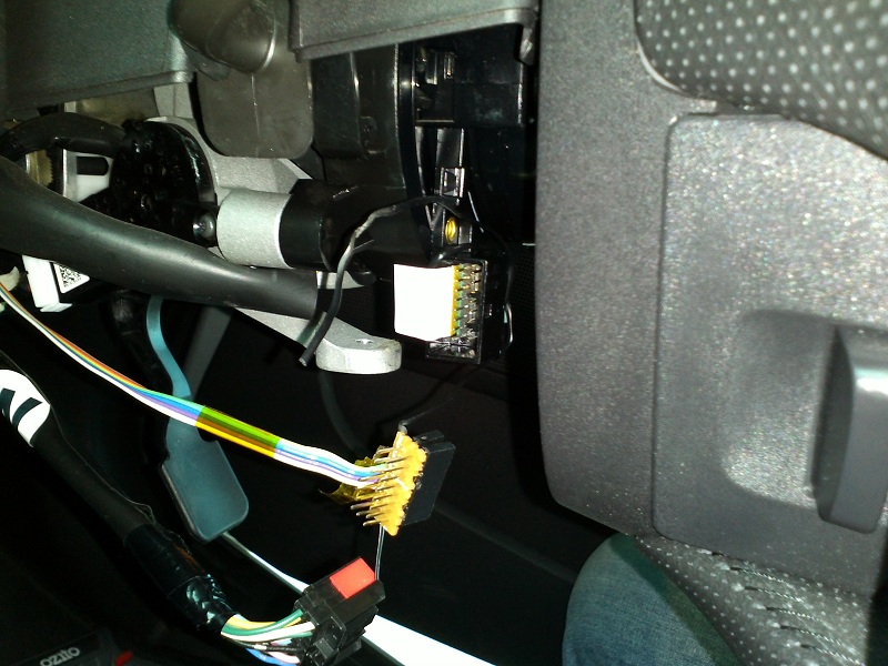 New interface board plugged in (this is a photo of my original prototype, I did have nicer circuit boards made up later as shown in the picture above): 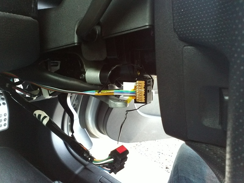 Original plug, back where it needs to be with the cable tie wrapped around it all [through the vertical centre of the plugs wires] ensuring it won't come loose while driving:  Ribbon cable [my prototype used coloured ribbon cable, not grey like in the other photos] threaded through the centre console. The black top cover of the centre console just pulls up and off for access: 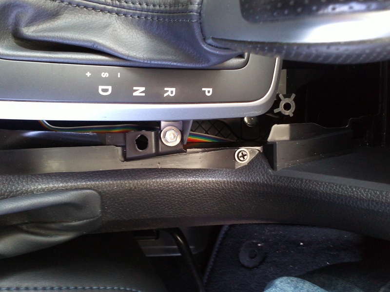 Inside the gear shifter module... I obviously didn't want to completely rip out the centre console to get this working so squeezing the leather trim edges of the shifter inwards at the centre and pulling it up gains access to the inside here:  To get access to the back of the transmission's connector, I used the handle (non sharp) end of a screwdriver and prised/pushed it toward the passenger side to unhook it from its mount. Then pulled up on the wires coming from the gear shift circuit board to move it into a suitable position to work on. Using some long nose pliers, I slid in the thick copper wire shown in pictures above and they are held in place by friction. Once done, I threaded the short cable through/underneath, and out the back of the shifter module. Connector C-318: |--------------| |BP|B.|BR|GR|LY| |LR|..|..|SB|G.| |--------------| ...|_......_| My 6 Pin Plug for the Paddle Shifter mod coming out from the gear plug: +12v (green/G) N/C GND (black/B) MGATE (blue/SB) TIP+ (grey/GR) TIP- (brown/BR) The cable looks like this, so I can easily see the missing pin to make sure I don't plug it in backwards: ---| ...|\____ ---|_____~ ---| ____~ ---|/ ---| (Had to replace spaces with dots for that to show correctly.) (Leave unconnected) Black+Grey/BP Light-Red/LR Light-Yellow/LY The nice thing about the +12v wire here is it's the battery saving power source - so the new circuit all turns off after 15 minutes once I stop driving: 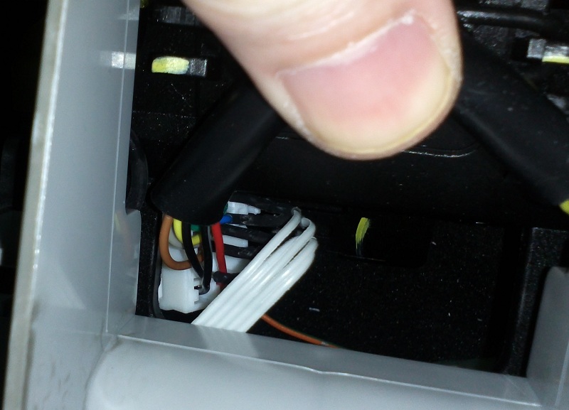 Both cables through the console and to my microcontroller: 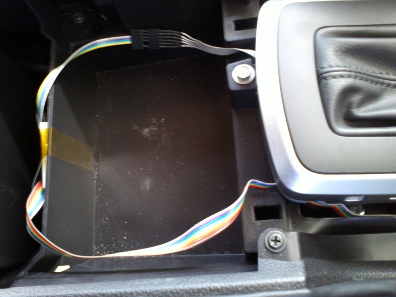 Tape the microcontroller in place with some strong kapton electrical tape:  Those two ribbon cables were later taped to the side walls so they were not moved when putting back the black centre console cover. The firmware I programmed does some nice things... All the steering wheel buttons work as they normally would when I'm in automatic mode. When in manual mode though, I figure I'm probably not interested in turning on cruise control or playing with the stereo source mode... So those paddle buttons now control gear shift up/down. All the other buttons continue to work as normal (volume / cruise resume etc.) at all times. If I'm using the original gear shifter for +/- (for example, while turning a corner when the steering wheel is upside down) it will very temporarily lock out the new paddle shifter signals. The paddle shifters themselves will only send a very short once off signal to the gear box, meaning I can continue to hold those buttons and not worry about the original shifter conflicting if also used soon after (it will override what was last sent to the gearbox). If, somehow, (and I've not knowingly managed to do this myself) I send a gear shift change using the new paddle shifters, and then also, slightly afterwards but within that very short time frame of the microcontroller's once off signal, send an opposite signal using the original shifter, the microcontroller will sense it and almost immediately discontinue the paddle shifter's signal early. I suspect the AT unit will do a 2nd check (or more) before engaging limp mode, but it will no longer see the two signals occurring at once by that time. The very first time I drove my car with it all set up, ignoring the air bag warning that went off (which took 3 hours to work out why), I found it difficult to control. I was constantly in the wrong gear, clumsily trying to get it corrected. As soon as the wheel was turned slightly, I didn't know which button to press to change gear. Then, with about 10 minutes of driving (going for a longer drive after fixing the air bag warning issue) it all sunk in... I now love it and I'm not going back.  Oh, some last comments, it's not possible in the firmware logic I wrote for the very short up/down signals [from my microcontroller] to the gear box to happen "at the same time" [by pressing both up and down shift on the steering wheel buttons] as the left/right button logic is tested and processed sequentially not asynchronously. I.E. one may occur, then the other may occur, but never both at the same time. Since I have previously been in a "panic situation" of wanting to slow down in an emergency [another story, another car  ] holding both buttons in panic will allow the "down shift" to override the "up shift". Safety first ] holding both buttons in panic will allow the "down shift" to override the "up shift". Safety first  Parts for this kit cost me around $75, I ordered some of the more expensive bits from China, it would be about $110 if purchased in Australia. The professional circuit boards I designed and then had made in China blew out that budget even more. The newer model without relays, that I'm testing now, costs about $30 in parts ($75 if bought in Australia) but then I wanted a nice circuit board for it too. It also takes me about 3 hours to assemble either version, and some more time still to fully test them on the workbench so I'm confident it won't hurt my car. I think if I were to make them for sale though, it would have to be a little overpriced for what it is because it takes so much time and effort, which is a shame. It also takes around an hour to install, which is mostly bent over the driver's seat, trying to use pliers to push in the thick copper wire into the back of that socket, while resting on my elbows! The steering wheel part isn't as bad, but threading the ribbon cable through the console was a bit hit and miss. Great fun though 
|
||
|
|

|
| 8 users like this post: |
|
|
#35 | ||
|
Away on leave
Join Date: Apr 2019
Location: ACT
Posts: 1,735
|
Just a quick update, so I don't spread any untruths...
This is the picture of the clock-spring connector I posted previously from the wiring manuals:  This is the connector I hadn't seen until today, which is shown right at the back of the PDF covering the MK2 wiring (2011/05 onwards):  So they did swap around the ground and signal wire for the cruise control buttons. Damn, only my first boards (that have no polarity requirement) will work on a MK1 unless I do some messy rewiring for the newer board. That extra wire I see in my harness is for the "Push to Talk" button as well, not that I've got the button - but I wonder if it would work if I did. Although the schematic says pin 1B is used by the airbag along with the 4 other pins, I don't think it really does as it makes no sense to source power through a relay coil? |
||
|
|

|
| 2 users like this post: |
|
|
#36 | ||
|
Away on leave
Join Date: Apr 2019
Location: ACT
Posts: 1,735
|
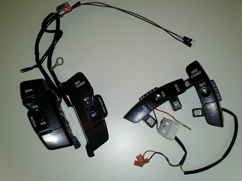
I was contacted by Ren a few weeks ago (AFF member 2.8L Hilux) about my flappy paddle project and he mentioned he had a BF Falcon with a ZF! (Awesome.) It got me thinking, it shouldn't be too hard to make it work on a BF, all I needed to know was the steering wheel button's resistances. He said the BF buttons were a slightly different configuration to the FG's so he thought the ones to re-map should be seek and resume-coast. I wasn't 100% convinced, until I received my next package from ebay in the mail (at half cost of the FG ones):
 (Yeah, I know, two sets of flawless looking buttons sitting in my R&D box.) So I went about repeating the process. Pulled out the red-wire-pin to measure and searched for some connectors that closely matched (I'm sure I know the brand, but I went with some different ones that had identical dimensions): 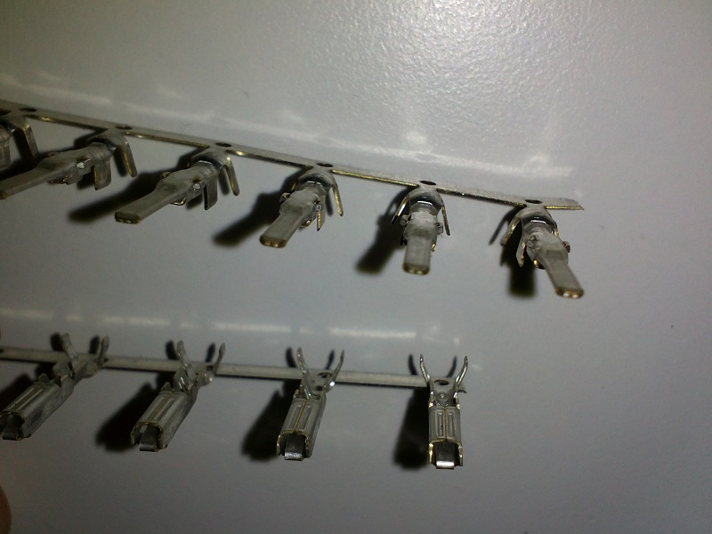 Which are 345807-1 & 345206-1 models from the 070 econoseal III contact line of products. I had taken a leap of faith that the clock-spring connectors would all be the same, which turned out to be true. So, having tested the buttons with my meter, picked the correct resistor values to make an R-to-R network that matched, and measured the new values with the microcontroller.. I created a kit for Ren all programmed up:  A few less resistors were needed, and one less transistor too. You can hardly see it, but there's a grey wire loop on the left of the blue circuit board folded under the green one, if it's cut, then the device will revert back to the mode/cruise buttons for shifting just in case thumbs are not as good as fingers  These are the instructions I supplied: 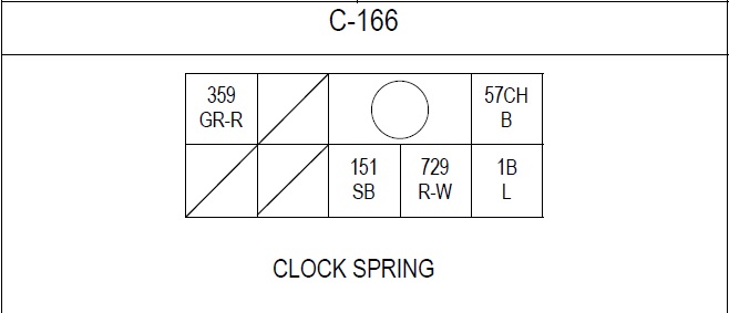 Plug connector from car-computers to the Clockspring socket front view: .----- ----- ----------- ------ | 359 |.....|.....O.....| 57CH.| .----- ----- ----- ----- ------ |.....|.....| 151 | 729 |..1B..| .----- ----- ----- ----- ------ Clockspring's socket receptacle front view: (mirror view to the plug above) .------ ----------- ----- ----- | 57CH |.....O.....|.....| 359 | .------ ----- ----- ----- ----- |..1B..| 729 | 151 |.....|.....| .------ ----- ----- ----- ----- Clock Spring Plug/Socket wire numbers and their function: 359 (GR-R) = Ground [Cruise Control] 151 (SB) = Signal [Cruise Control] 729 (R-W) = Signal [Radio] 57CH (B) = Ground [Radio & Horn] 1B (L) = +12V [through Horn relay coil] My ribbon wire and which side & pin they connect to: 1 = Ground Radio Buttons Side 57CH socket\_+BLACK WIRE 2 = Ground Radio Device Side 57CH pin..../ FOR THE HORN 3 = Signal Radio Buttons Side 729 socket 4 = Signal Radio Device Side 729 pin 5 = Signal Cruise Buttons Side 151 socket 6 = Signal Cruise Device Side 151 pin 7 = Ground Cruise Buttons Side 359 socket 8 = Ground Cruise Device Side 359 pin And 1 single wire for the +12v horn relay connection which my device doesn't need. You can see the ribbon wire has wires 1 & 2 connected with a thicker black wire, so that's where to start. Once it's all done, I guess, use some electrical tape to secure it in place so if you pull on it, it doesn't all come undone. I.E. tape the end of the ribbon wire to the car's existing harness. If you don't get it right (and as long as the +12v hasn't been plugged in incorrectly) there should be no effect on the car other than the radio / cruise functions being activated immediately or when accessories is on. Just try again. Maybe only plug that single +12v wire in once you're done? That's the only one that can possibly damage my device - and if it's wrong, the horn will probably go off right away giving you the scare of your life! Ren did send through one image that looked familiar to me, but wasn't what I had seen before: (I don't know how he got such good access to the plug! The FG has it locked away...) 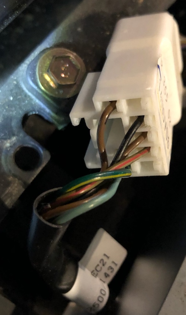 Which is the BF MKII gear shifter plug, which has less wires and different colours to what the FGII has. I could see the wires that were there are in the same place as what I had described before though, for the ones I needed, and the circuit diagram I have for the BF said they were the ones to use, so I suggested that looked OK to continue. Both Ren and I thought the copper wire inserts were a tight fit, but long nose pliers worked well for us both. And the result? See the last post on page 2 of Ren's V8 BFII Fairmont Ghia show and shine thread: http://wwww.fordforums.com.au/showth...1478318&page=2 Anyhow, it's good to know that quite a lot of the parts in our cars share such similar heritage. Although Ford was having a "brown wire" day when the BF was being designed! I'm really glad Ren had a good experience with this mod. He paid me more than I had asked, so I got a free lunch! Thanks man! Not wanting to say, but $200 + overnight-postage of $11.55 was my estimate for what it cost me in parts and time to make it for him. I might be convinced to make some more, if the instructions are not scary to whoever's interested. |
||
|
|

|
| 4 users like this post: |
|
|
#38 | ||
|
FF.Com.Au Hardcore
Join Date: Feb 2008
Location: Perth, Northern Suburbs
Posts: 5,011
|
I have the organic system...
My brain is connected to my arms, works a treat |
||
|
|

|
|
|
#39 | ||
|
Away on leave
Join Date: Apr 2019
Location: ACT
Posts: 1,735
|
If you let me connect some wires to your head, I'm sure I can make it even more efficient for you! Trust me, I'm a professional!
|
||
|
|

|
| 5 users like this post: |
|
|
#40 | ||
|
FF.Com.Au Hardcore
Join Date: May 2014
Location: Melbourne
Posts: 532
|
just sent you a PM JasonACT
__________________
Ben 2008 TTG current ride https://flic.kr/s/aHsmM1PB26 former ride https://flic.kr/s/aHsmM1PK1Y former former ride https://flic.kr/s/aHsmM1N7Nq |
||
|
|

|
| This user likes this post: |
|
|
#41 | ||
|
FF.Com.Au Hardcore
Join Date: Feb 2009
Location: Newcastle
Posts: 513
|
Clocked about 1,500kms so far with the mod with zero issues.
I can't believe this isn't more popular!
__________________
Ford Territory Titanium | SZ Mk1 4.0L Ford Falcon G6ET | FG Mk1 |
||
|
|

|
|
|
#42 | |||
|
FF.Com.Au Hardcore
Join Date: May 2014
Location: Melbourne
Posts: 532
|
Quote:
Just a question for you 2.8L Hilux, do you prefer the mode/cruise buttons to shift? or the seek/resume? and can you change between the two?
__________________
Ben 2008 TTG current ride https://flic.kr/s/aHsmM1PB26 former ride https://flic.kr/s/aHsmM1PK1Y former former ride https://flic.kr/s/aHsmM1N7Nq |
|||
|
|

|
| This user likes this post: |
|
|
#43 | |||
|
FF.Com.Au Hardcore
Join Date: Feb 2009
Location: Newcastle
Posts: 513
|
Quote:
Guess it all depends on where you normally hold your hands on the wheel. I'm pretty sure Jason can program the module to your choice, but you can't toggle between the two.
__________________
Ford Territory Titanium | SZ Mk1 4.0L Ford Falcon G6ET | FG Mk1 |
|||
|
|

|
|
|
#44 | |||
|
Miami Pilot
 Join Date: Jan 2005
Location: ACT
Posts: 21,703
|
Quote:
__________________
-----------------------------------------------------------------
The Hammer: FG GTE | 376rwkw | 1/4 mile 11.793 @ 119.75mph 1.733 60' (4408lb) 1 of 60 FG MK1 335 GTEs (1 of 118 FG Mk 1 & 2 335 GTEs). Mods: Tune, HSD/ShockWorks, black GT335 19Ē staggered replicas with 245 & 275/35/19 Michelin Pilot sport 5s Daily: BF2 Fairmont Ghia I6 ZF, machine face GT335 19Ē staggered Replicas with 245s and 275s, Bilsteins & Kings FPV 335 build stats: <click here> Ford Performance Club ACT |
|||
|
|

|
|
|
#45 | ||
|
FF.Com.Au Hardcore
Join Date: May 2014
Location: Melbourne
Posts: 532
|
I was thinking that.
Also was thinking of making a jumper loom for the clock spring with the factory plugs from a wreck. Would make it a bit neater
__________________
Ben 2008 TTG current ride https://flic.kr/s/aHsmM1PB26 former ride https://flic.kr/s/aHsmM1PK1Y former former ride https://flic.kr/s/aHsmM1N7Nq |
||
|
|

|
| This user likes this post: |
|
|
#46 | ||
|
Away on leave
Join Date: Apr 2019
Location: ACT
Posts: 1,735
|
FYI - You can cut the grey wire loop I solder in on the BF versions and after the car is off for 15 minutes (and my module resets) next time you start it will revert to MODE/CRUISE for the shifter buttons.
|
||
|
|

|
| This user likes this post: |
|
|
#47 | ||
|
FF.Com.Au Hardcore
Join Date: May 2014
Location: Melbourne
Posts: 532
|
Installed it for the final time after modifying it slightly. I added some clock spring plugs and sports shifter plugs to Jason's original device to make it more plug and play.
Thx for making one up and sending it so quickly Jason, your device works a treat. These are the plugs I made up. Shifter plugs on the left, clock spring plugs in the middle and the shifter plug to Jason's device is the one on the far right 
__________________
Ben 2008 TTG current ride https://flic.kr/s/aHsmM1PB26 former ride https://flic.kr/s/aHsmM1PK1Y former former ride https://flic.kr/s/aHsmM1N7Nq |
||
|
|

|
| 2 users like this post: |
|
|
#48 | ||
|
Away on leave
Join Date: Apr 2019
Location: ACT
Posts: 1,735
|
Ha ha ha! Awesome man!
|
||
|
|

|
|
|
#49 | ||
|
Away on leave
Join Date: Apr 2019
Location: ACT
Posts: 1,735
|
For anyone interested, I spent some time this weekend making up one of each type..
http://wwww.fordforums.com.au/showth...09#post6312909 |
||
|
|

|
| This user likes this post: |
|
|
#50 | ||
|
Away on leave
Join Date: Apr 2019
Location: ACT
Posts: 1,735
|
I had a small win today, swapped over my black set of buttons to some nice looking silver ones, it took about 45 minutes as I luckily had all the tools needed:
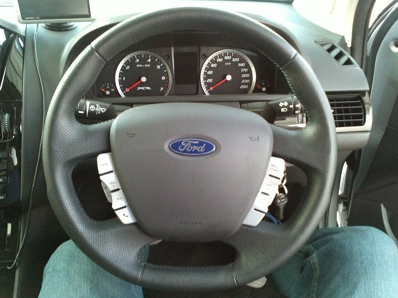 Anyone needing to know the airbag plug arrangement (where did the rust come from?): 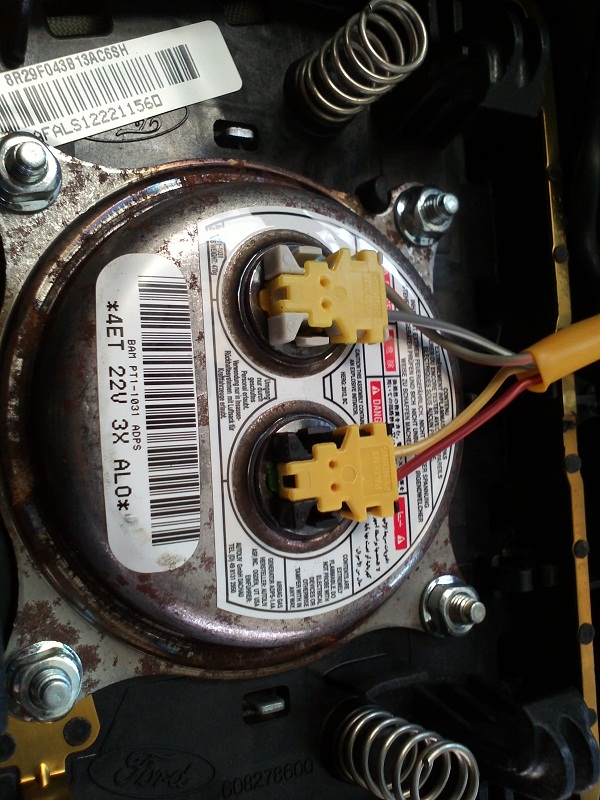 And now I have a spare steering wheel to study... Had a discussion with someone with some great ideas, came up with this prototype 3D printed paddle... Doesn't really work though, I need to think more about adding a hinge - currently this very basic design hinges on the button which makes the top paddle area go outwards rather than forward towards the driver. 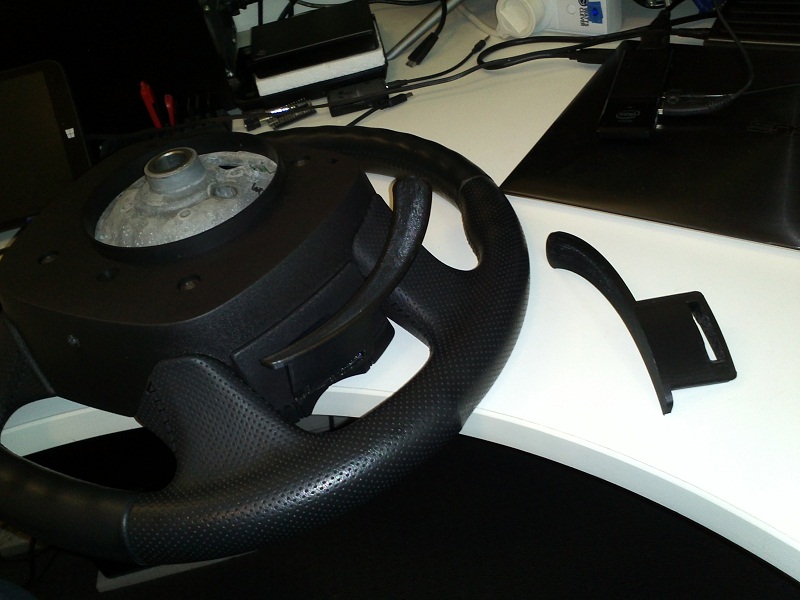 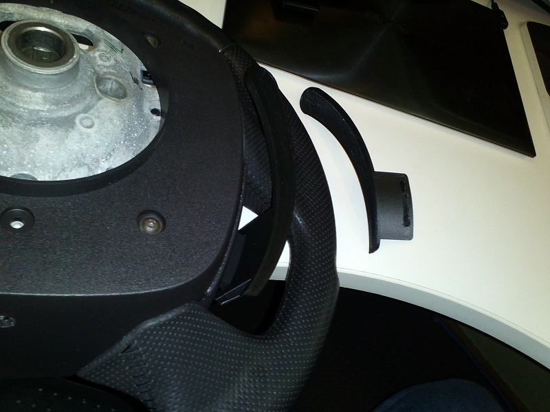 It clears the stalks though, so that's good. I'm open to suggestions too 
|
||
|
|

|
|
|
#52 | ||
|
Away on leave
Join Date: Apr 2019
Location: ACT
Posts: 1,735
|
I have been looking for 3rd party paddles, but they are very expensive and there doesn't seem to be a lot to choose from. If I can find some reasonably priced ones, I could then start designing a 3D printed attachment for joining them to the wheel.
I'll check those out though, thanks. |
||
|
|

|
|
|
#53 | ||
|
🚫⏰4️⃣🐃💩
Join Date: Sep 2012
Posts: 1,901
|
Mazda has had paddle shift in their cars since early 2000's. The RX-8, Mazda6, Mazda3, CX-* range all have peddle shift. And since Mazda and Ford were at the time, still an item, maybe (hopefully) some of the gear is interchangeable (??).
  
|
||
|
|

|
| This user likes this post: |
|
|
#54 | ||
|
FF.Com.Au Hardcore
Join Date: Feb 2008
Location: Perth, Northern Suburbs
Posts: 5,011
|
|
||
|
|

|
|
|
#55 | ||
|
Away on leave
Join Date: Apr 2019
Location: ACT
Posts: 1,735
|
I'm not about to argue with one of the smartest & funniest blokes on the planet.
Nice find Dazza. |
||
|
|

|
|
|
#56 | ||
|
FAWD - No Boundaries
 Join Date: Jun 2010
Location: Adelaide
Posts: 8,129
|
I actually got my paddle shift working a couple years ago now... and I used the paddles from a 2010-12 Ford Taurus. I fitted them onto an FG wheel
https://www.flickr.com/photos/101170...in/photostream https://www.flickr.com/photos/101170...in/photostream The wiring pins for the U.S. Ford' clockspring are the same as the FG's... so they just needed to be depinned from the Taurus' plug and reinserted into the FG's. I did have to heat up the column stalks to bend them away from the paddles a bit.. but not a great deal ! https://www.flickr.com/photos/101170...in/photostream I've got the ZF 6spd in the Wagon... and it took a while to work out a reliable interface that just plugs into the auto stick plug... but what we ended up with works really well ! https://www.flickr.com/photos/101170...in/photostream Great to see someone else having a go !!  Dhru
__________________
View My Build thread 22 DJR Shell V-Power Mustang Eskymobile (my first EV) 07 BF2 AWD Falcon Wagon (Daily driver) 04 BA Falcon 1Tonner Ute (New Project) 03 BA Falcon Wagon (Spare) 98 NL Fairlane Ghia V8 (Weekend cruiser) 70 VG paddock racer (Cain it til it breaks.. fix it.. Cain it all over again !)
Last edited by Gothefalcon; 28-08-2019 at 02:23 AM. |
||
|
|

|
|
|
#57 | ||
|
Away on leave
Join Date: Apr 2019
Location: ACT
Posts: 1,735
|
That's awesome Dhru! Nice work, and I really like the photos.
I may have also found something suitable and cheap for a custom 3D printed housing: http://www.vagmall.com/AUDI%20Steeri...ddle%20shifter  
|
||
|
|

|
| This user likes this post: |
|
|
#58 | ||
|
FAWD - No Boundaries
 Join Date: Jun 2010
Location: Adelaide
Posts: 8,129
|
From memory... I think I paid about $130 AUD to get a 2nd hand Taurus wheel sent out from the States !?? But the overall design of the wheel looked similar to the FG's, so I took a punt. The FG's spoke design is a similar shape (in section) but they're not quite as long as the Taurus' spokes.
Still... I was able to get them to fit ok.  Sure... if you can find/make an better alternative that works, is cheaper and doesn't need the column stalks adjusted, that would be ideal ! Keep up the good work  D
__________________
View My Build thread 22 DJR Shell V-Power Mustang Eskymobile (my first EV) 07 BF2 AWD Falcon Wagon (Daily driver) 04 BA Falcon 1Tonner Ute (New Project) 03 BA Falcon Wagon (Spare) 98 NL Fairlane Ghia V8 (Weekend cruiser) 70 VG paddock racer (Cain it til it breaks.. fix it.. Cain it all over again !)
|
||
|
|

|
| This user likes this post: |
|
|
#59 | ||
|
Away on leave
Join Date: Apr 2019
Location: ACT
Posts: 1,735
|
With postage, those buttons (which are in US$) come to about AUD$56 - so not too bad.
I'm not sure if the stalks will be a problem, mine don't seem to be angled the same way, or is that the angle of my photo? Using the pull-toward-driver functions does bring them much closer though: 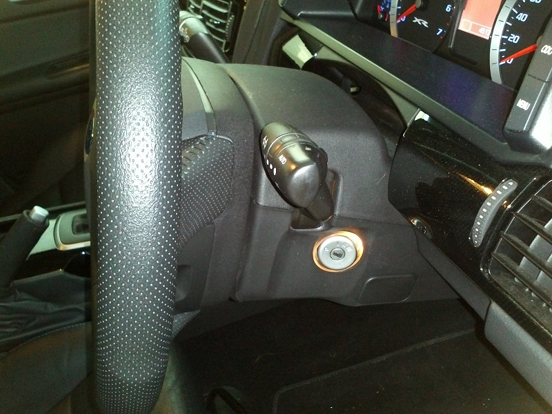 It may be a problem for the windscreen washer. I don't normally flash my lights, so I can live without that. I'll find out, I suppose, when the buttons arrive and I can see how thick (or rather, hopefully thin) they are. Now to play the waiting game. 
|
||
|
|

|
| This user likes this post: |
|
|
#60 | ||
|
FAWD - No Boundaries
 Join Date: Jun 2010
Location: Adelaide
Posts: 8,129
|
You can see here that it's not the end of the stalks which are the problem... it's where the stalks bend to level out. This area is quite close to the back of the wheel already...
 IMG_0627 by Gothe Falcon, on Flickr IMG_0627 by Gothe Falcon, on Flickr 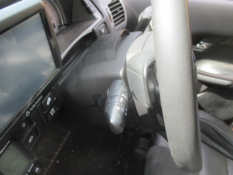 IMG_0618 by Gothe Falcon, on Flickr IMG_0618 by Gothe Falcon, on FlickrSo when I reworked the stalks, I actually heated up the mid section and moved the bend away from the back of the wheel, but left the end of the stalk in the original position (within reach of your fingers)...  IMG_0629 by Gothe Falcon, on Flickr IMG_0629 by Gothe Falcon, on Flickr IMG_0630 by Gothe Falcon, on Flickr IMG_0630 by Gothe Falcon, on Flickr This had the effect of aligning the top of the stalk more parallel which the back of the wheel spokes (giving me the room I needed for the paddles) without loosing any functionality of the stalks (by being too close to the back of the wheel at the bend)... or too far away from your finger tips (Had I just bent the whole thing back). It's less a bending of the stalks... and more a twisting of them, I s'pose !?? The tape etc you can see in the pics, was there to help bend both halves of the stalk together, the same amount (the back of the stalk can be removed for wire access). These Taurus paddles aren't actually as chunky as they look... as in... they don't take up much space at all. It's just that when you pull the stalks towards you, there's not a lot of room left (before you even fit the paddles), in that area around the stalk's bend. Hope that made sense !?? D
__________________
View My Build thread 22 DJR Shell V-Power Mustang Eskymobile (my first EV) 07 BF2 AWD Falcon Wagon (Daily driver) 04 BA Falcon 1Tonner Ute (New Project) 03 BA Falcon Wagon (Spare) 98 NL Fairlane Ghia V8 (Weekend cruiser) 70 VG paddock racer (Cain it til it breaks.. fix it.. Cain it all over again !)
|
||
|
|

|
| This user likes this post: |